NSX-T Series: Part 3 – Planning NSX VXLAN
In this NSX-T Series: Part 3 – Planning NSX VXLAN blog, we will discuss more on the Planning of NSX VXLAN, and what are the pre-requisite which should be collected and planned.
But if you want to start from beginning you can refer my previous part of the Series
NSX-T Series : Part 1 -Architecture and Deploy
NSX-T Series : Part 2 – Adding Compute Manager
Introduction
In the previous part we discussed how we added Compute Manager to NSX Manager, in this part, we will discuss how to decide the planning of NSX VXLAN and add the IP Address pool for the purpose of VTEP on ESXi level.
TEP or VTEP
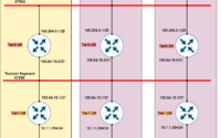
When the VxLAN concept was introduced on RFC: 7348 there were no terms like TEP the devices which introduce VXLAN were referred to as VTEP. Conceptually both TEP/VTEP are the same which encapsulates and decapsulates the Vxlan header is called TEP/VTEP, which could be a switch or a server.
It was also mentioned the network between TEP/VTEP devices can be on L2 or L3 network. If it is an L2 network it could be any medium that gives L2 Bridging. If it is an L3 network then for flooding multicast can be used so it creates a loop-free path. ( Very same process followed in Fabric Path earlier ). It is well explained on older videos of Cisco Live which gives you base concepts of benefits of VXLAN and how it is implemented in real cases.
The whole myntra is to make sure the TEP/VTEP are connected with each other, which could be any solution either ACI or NSX. Only the difference among them how they advertise the information of endpoints to related TEP/VTEP.

In ACI we refer TEP as Leaf Switch and Spine which handles the switch fabric with BGP Route-Reflector. I would highly recommend following some fantastic videos from Cisco, it goes deep dive on BGP EVPN if you want to explore more because beneath the concept remains the same.
When we talk about NSX-T it expects from infra MTU must be at least 1600 ( larger is better ! ), and if the subnet of the VXLAN vmk is different it should be routed across.
What you get on TOR and Uplink Network
When we plan VMware over any infra the basic requirement is to fill out the VLAN requirement which includes Management, vMotion, NFS, VSAN, and Data Plane ( Non-NSX traffic or NSX VXLAN traffic ).
It all depends on what infra you get while planning the greenfield or brownfield environment and need to always plan on the throughput expected from NIC levels, and define them accordingly on the DVS level.
It could be any medium: VLAN, EPG ( ACI model ), Port-Group ( Nested ESXi ), L2GW ( OpenStack network). All this component refers to the same logical network.
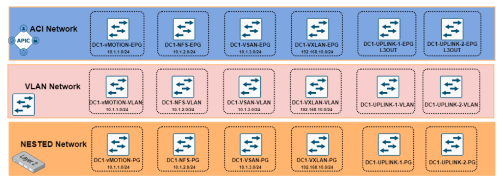
How I simulated the NSX VLAN
In my previous blogs I have shared how I setup home lab, you can refer those series
VMware Home Lab: NUC NUC10i7FNH part – 1
VMware Home Lab : NUC NUC10i7FNH Part 2
I have used nested ESXi network to setup NSX workloads and mapped the uplinks to platform port-group and gives real scenario environment.
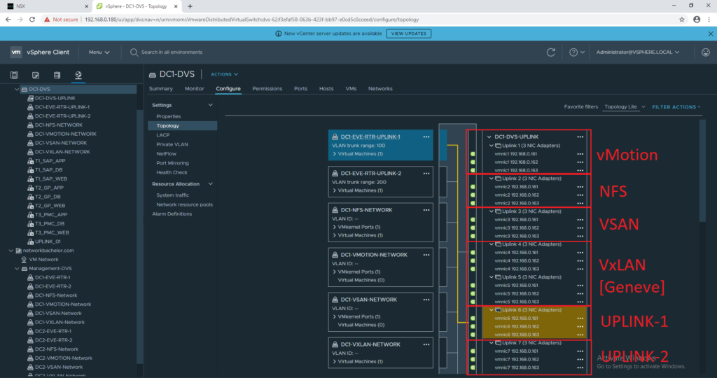
On DVS level it is required to increase the MTU otherwise you will face error while adding the ESXi. You can increase the MTU as per the ToR/Uplink Switch configuration.

NSX VXLAN/GENEVE
After setting up the ESXi as per the uplinks mapping my lab Esxi network will look like follows:

On NSX Manager to add Ip Address Pool for VTEP can be added via the Networking > IP Address Pools > IP Address Pools (Subnet) tab.
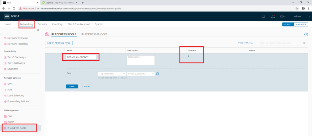

This subnet will be used by ESXi for VxLAN encapsulation and will be installed on ESXi vmk10. ( This will be installed when ESXi will be added to NSX which we will discuss in further blog)

The geneve ( NSX VXLAN ) encapsulation will be used as per the RFC explained above.
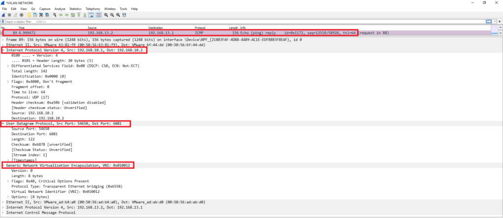
Summary & Next Steps
In this post, we discussed the VXLAN preparation steps for ESXi and other Nodes which will be used for VTEP purpose. In the next blog, we will discuss how we will prepare the ESXi host for NSX.

Excellent article